Track geometry developed around representative production components.
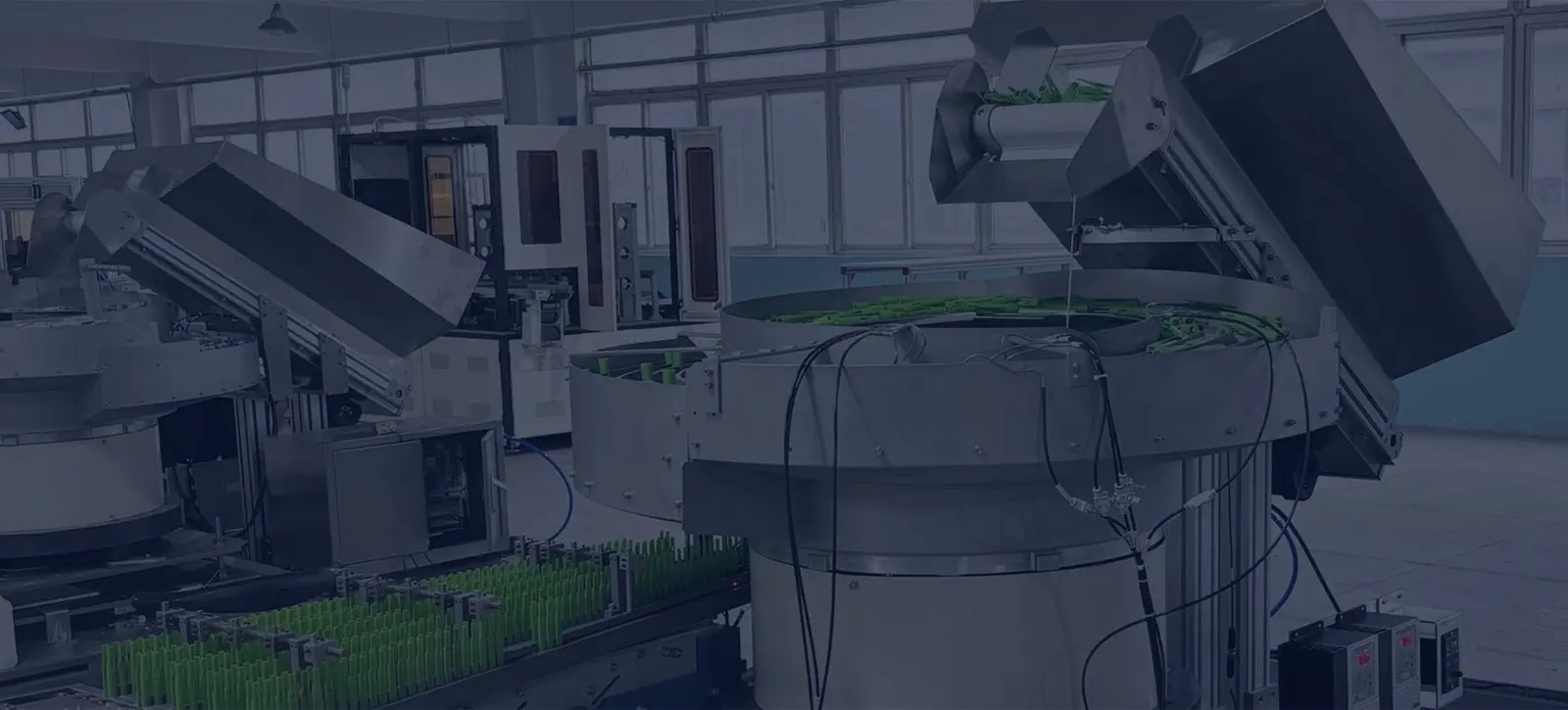
Linear vibratory feeding · UK project support
Linear feeder systems that keep every component moving in the right direction.
Custom linear feeder systems, vibratory tracks and inline component feeders engineered to transfer, buffer and present oriented parts reliably to UK automation.
Application inputPart · orientation · rate · interface
Buffer length and queue behaviour matched to the downstream cycle.
Sensors, stops and escapements designed with the receiving machine.
Trial and acceptance criteria agreed around the real operating condition.
More than a straight conveyor
A / 01A stable bridge between orientation and the machine cycle.
A linear feeder receives components from a bowl, step, centrifugal or other presentation system and moves them along a purpose-designed track while preserving the accepted orientation.
The track can also create a controlled queue, isolate upstream variation and hold enough correctly presented parts for the downstream process to continue through short feeder interruptions.
Linear feeder: a driven inline track used to convey, buffer, orient or meter components in a controlled path before an automated process.
Application engineering guidance
Engineer each part of the feed path deliberately.
Output is rarely determined by the drive alone. Component contact, track geometry, queue pressure, sensor logic and final release all influence sustained performance.
01
Linear vibratory feeders
Inline vibratory drives and tracks for controlled transfer, orientation retention and part availability.
View application guidance →02Track design & tooling
Purpose-designed profiles, rails, covers and contact finishes that keep parts stable and correctly presented.
View application guidance →03Buffer & accumulation
Size the oriented queue around recovery time, machine demand and acceptable back pressure.
View application guidance →04Controls & sensors
Coordinate drive output, track occupancy and machine demand with clear signals and fault logic.
View application guidance →05Escapements & machine interface
Separate, stop and release one part—or a defined group—at the exact position required downstream.
View application guidance →06Component trials & FAT
Prove behaviour, sustainable accepted output and recovery using representative production parts.
View application guidance →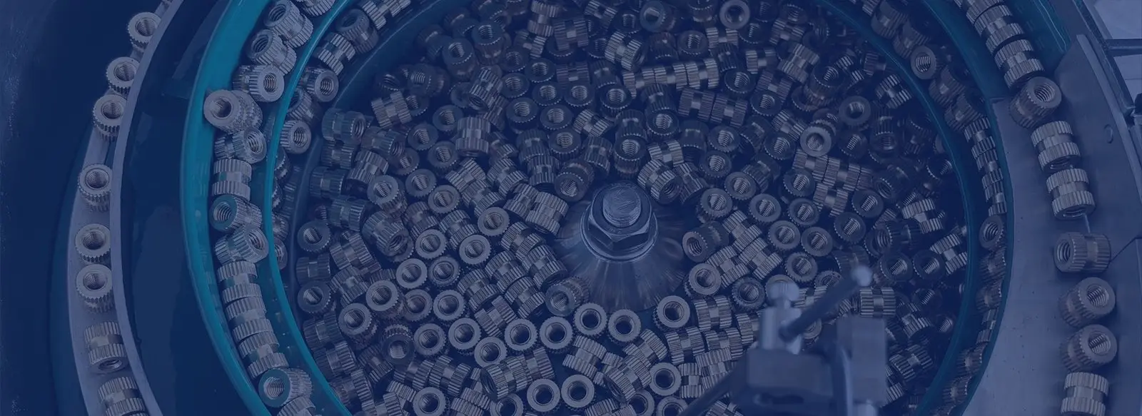
Complete feeding sub-systems
From bulk supply to one controlled component at a time.
Linear tracks are commonly integrated with vibratory bowls, step feeders, bulk hoppers, controls, support frames and guarding. Treating the path as one system makes it easier to manage replenishment, recovery and line signals.
Every proposal is based on the component, required orientation, sustainable accepted rate and machine interface—not a catalogue width or headline speed alone.
- Single-lane and multi-lane track concepts
- Track-full, low-level and jam sensing
- Adjustable or change-part tooling where suitable
- PLC handshakes and downstream-ready signals
- Support frames, guarding and acoustic treatment
A practical project route
Define it. Trial it. Integrate it.
Application review
Part variants, orientation, rate, environment and receiving-machine details are assessed.
Sample trial
Representative components are used to confirm behaviour, contact strategy and likely tooling.
Detailed engineering
Track, sensors, controls, frame and machine interface are coordinated as one system.
FAT & handover
The agreed test is run, results recorded and installation requirements confirmed.
Component families
Linear feeding for repeatable automated presentation.
01
Fasteners & fixings
Screws, nuts, washers, rivets and inserts presented for assembly, counting or packaging.
View application guidance →02Automotive components
Clips, retainers, connectors and mouldings delivered to automated assembly and inspection.
View application guidance →03Electronics & connectors
Housings, terminals and small moulded parts controlled around pins, contacts and static-sensitive features.
View application guidance →04Caps & closures
Plastic and metal closures buffered and presented for capping, lining, inspection or packaging operations.
View application guidance →Buyer and engineering guides
Find the right answer for your feeding project.
Practical guidance for selecting, comparing, controlling and troubleshooting industrial inline component feeders.
01
Linear feeder systems
Understand the complete route from primary feeder to machine hand-off.
Explore complete systems →02Inline component feeders
See how industrial inline tracks preserve orientation and create useful buffers.
Explore inline feeders →03Selection guide
Choose from the component, accepted output, buffer and interface backwards.
Use the selection checklist →04Feeder controllers
Plan amplitude, frequency, sensor logic and PLC demand control.
Review control options →05Troubleshooting
Trace slow feed, jams, bounce, noise and intermittent stops safely.
Diagnose common symptoms →06Feeder vs conveyor
Compare vibratory tracks and belt conveyors by function; use the separate gravity-track guide for passive transfer.
Compare technologies →Specialist project guidance
Answers for the decisions that create real feeder enquiries.
Explore distinct engineering routes for parallel output, robotic pick points, multiple formats, inspection, delicate components, service and project budgeting.
01
Multi-lane feeders
Plan parallel tracks by accepted output per lane, balance, sensing and release.
Review multi-lane systems →02Robot pick presentation
Define datum, nest, sensing, handshake and recovery at the robot hand-off.
Plan the pick point →03Quick-change tracks
Compare adjustable guides, change parts and interchangeable tooling for component variants.
Plan repeatable changeover →04Track inspection
Inspect orientation, presence or critical features before a component is released.
Review inspection options →05Gentle, low-noise feeding
Control touch points, queue pressure, liners, isolation and acoustic treatment.
Protect sensitive parts →06Gravity track vs feeder
Choose passive or driven transfer from slope, part behaviour and queue stability.
Compare transfer methods →07Service and repair
Assess repair, retooling, replacement controls and the required production retest.
Prepare a service review →08Cost and quotation
Understand how parts, lanes, tooling, controls, testing and delivery change scope.
Build a comparable brief →09Medical components
Define contact, cleanability, inspection, documentation and customer-led qualification inputs.
Review the application →10Counting & batching
Plan singulation, one accepted count event, gate logic, container changes and batch evidence.
Define the count boundary →Common questions
Linear feeder questions, answered.
Practical guidance for an early project review. Final design and performance are confirmed against the actual application.
01What is a linear vibratory feeder?+
A linear vibratory feeder uses controlled vibration to move components along a straight, profiled track. It is commonly used to maintain orientation, create accumulation and present parts to an escapement, robot, assembly station or inspection process.
02Is a linear feeder the same as a conveyor?+
No. A conveyor normally moves products on a driven belt, chain or surface. A linear feeder typically uses vibration and a component-specific track to preserve orientation or control a queue. The correct technology depends on the part and the required hand-off.
03Can a linear feeder orient components?+
It can maintain an orientation created upstream and, in suitable applications, perform additional selection or orientation through track tooling. Complex random orientation is usually handled by a bowl, step, centrifugal or flexible feeding system first.
04How do you choose the track length?+
Track length is based on transfer distance, required buffer time, component pitch, queue behaviour, access and available footprint. Longer is not automatically better because excessive accumulation can increase back pressure or instability.
05What information is needed for a quotation?+
Send part photographs or drawings, all variants, dimensions and weight, material and finish, target sustained rate, required orientation, available space and details of the downstream machine interface.
Start with the component
Need a stable path to the next machine?
Send a part photo or drawing, the required orientation and sustainable rate. We will help define the right linear feeding approach.
Request an application reviewHow should a linear feeder connect a bowl to an assembly station?
Define the part orientation, required buffer and the final hand-off position. Review track length, transitions, escapement and demand signals with the upstream feeder and receiving machine. Trial full and empty track conditions, blocked demand and replenishment so that the delivered part remains suitable for the next operation.